Basic Steps for Using a Stepper Motor Encoder
1.Introduction to Stepper Motor Encoders
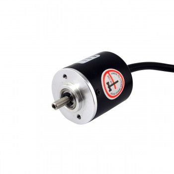
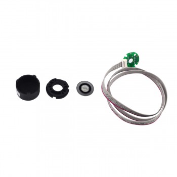
A stepper motor encoder is a device mounted on a stepper motor that provides a closed-loop feedback signal by tracking the speed and/or position of the motor shaft. This encoder ensures precise control and positioning of the stepper motor by monitoring motor parameters such as speed, distance, revolutions per minute (RPM), and position. The stepper motor itself is an open-loop system, which means that it does not require sensors to feed information back to the controller, so it may experience loss of steps in some cases. By adding an encoder to a stepper motor system, the ability to detect or even prevent loss of steps by providing feedback to the drive can be added. In this way, depending on how the operator programs the controller, the encoder feedback can verify the motor position, immediately detect motor stalls, prevent motor stalls, and create a closed-loop servo system.

2.Working Principle of Stepper Motor Encoders
The working principle of a stepper motor encoder is mainly to convert rotational displacement into a series of digital pulse signals, which can be used to control angular displacement. If the encoder is combined with a gear or lead screw, it can also be used to measure linear displacement. The encoder generates electrical signals that are processed by numerical control devices, programmable logic controllers, control systems, etc. These sensors are mainly used in machine tools, material processing, motor feedback systems, and measurement and control equipment. Specifically for stepper motors, the role of the encoder is to improve the positioning accuracy and control accuracy of the stepper motor, reduce errors and vibrations, and thus improve the reliability and stability of the entire system.
3.Basic steps for using stepper motor encoders
1.Wiring connection: First, the output signal of the encoder needs to be correctly connected to the control system. Encoders usually have a variety of wiring methods, such as four-wire and five-wire systems, and the specific wiring method depends on the type of encoder and the requirements of the control system. For example, in the five-wire wiring, brown is connected to 24 volts, blue is connected to 0 volts, black and white are connected to phase A and phase B respectively, which are used to control pulses and directions, and the orange wire (if any) is used as the Z phase for resetting or providing a pulse per revolution signal.
2.Control system integration: Connect the encoder signal to the control system of the stepper motor. This usually involves connecting the encoder output signal to the input of the controller, such as the high-speed counter input of the PLC (programmable logic controller). The control system needs to be able to identify and process the signals provided by the encoder, such as the number of pulses, direction, etc.
3.Closed-loop control: Closed-loop control is achieved using the feedback information from the encoder. The encoder can measure the actual rotation of the stepper motor and feed this information back to the control system. The control system calculates the deviation by comparing the set target and the actual feedback, and then adjusts the drive signal of the stepper motor to ensure that the stepper motor moves along the expected path and speed. This closed-loop control can improve the positioning accuracy of the stepper motor and the stability of motion control.
4.Parameter setting and calibration: Depending on the specific application requirements, the parameters of the control system may need to be set and calibrated. This includes setting the drive current, acceleration, deceleration time and other parameters of the stepper motor, as well as calibrating the zero point and range of the encoder to ensure the accuracy of the measurement and the precision of the control.
5.Fault diagnosis and maintenance: Fault diagnosis and maintenance may be required during use. By analyzing the feedback signal of the encoder and the status of the control system, problems in the operation of the stepper motor, such as loss of step and overshoot, can be discovered and solved in a timely manner.

4.How to choose a suitable stepper motor encoder
1.Motor specifications and encoder compatibility: Make sure that the selected encoder matches the specifications of the stepper motor, including the size of the motor, shaft diameter, etc., to ensure that the encoder can be firmly mounted on the stepper motor.
2.Encoder type: Select the appropriate encoder type according to the application requirements, such as incremental encoder or absolute encoder. Incremental encoders are suitable for applications that require continuous monitoring of position changes, while absolute encoders are suitable for applications that need to know the absolute position.
3.Resolution: The resolution of the encoder determines the minimum movement it can detect. High-resolution encoders can provide more accurate position feedback and are suitable for applications that require high-precision control.
4.Interface and communication: Consider the encoder's interface type (such as analog output or digital output) and the convenience of communicating with the control system. Digital output encoders generally provide more accurate signal transmission and simpler data processing.
5.Durability and environmental adaptability: According to the special requirements of the application environment (such as temperature, humidity, vibration, etc.), choose an encoder that is durable and adaptable to the specific environment.
6.Brand and quality: Choose products from well-known brands, which are usually market-proven and have good quality and after-sales service guarantees.
7.Cost consideration: According to the project budget, find a balance between performance and cost, and choose an encoder with high cost performance.
A stepper motor encoder is a device mounted on a stepper motor that provides a closed-loop feedback signal by tracking the speed and/or position of the motor shaft. This encoder ensures precise control and positioning of the stepper motor by monitoring motor parameters such as speed, distance, revolutions per minute (RPM), and position. The stepper motor itself is an open-loop system, which means that it does not require sensors to feed information back to the controller, so it may experience loss of steps in some cases. By adding an encoder to a stepper motor system, the ability to detect or even prevent loss of steps by providing feedback to the drive can be added. In this way, depending on how the operator programs the controller, the encoder feedback can verify the motor position, immediately detect motor stalls, prevent motor stalls, and create a closed-loop servo system.

2.Working Principle of Stepper Motor Encoders
The working principle of a stepper motor encoder is mainly to convert rotational displacement into a series of digital pulse signals, which can be used to control angular displacement. If the encoder is combined with a gear or lead screw, it can also be used to measure linear displacement. The encoder generates electrical signals that are processed by numerical control devices, programmable logic controllers, control systems, etc. These sensors are mainly used in machine tools, material processing, motor feedback systems, and measurement and control equipment. Specifically for stepper motors, the role of the encoder is to improve the positioning accuracy and control accuracy of the stepper motor, reduce errors and vibrations, and thus improve the reliability and stability of the entire system.
3.Basic steps for using stepper motor encoders
1.Wiring connection: First, the output signal of the encoder needs to be correctly connected to the control system. Encoders usually have a variety of wiring methods, such as four-wire and five-wire systems, and the specific wiring method depends on the type of encoder and the requirements of the control system. For example, in the five-wire wiring, brown is connected to 24 volts, blue is connected to 0 volts, black and white are connected to phase A and phase B respectively, which are used to control pulses and directions, and the orange wire (if any) is used as the Z phase for resetting or providing a pulse per revolution signal.
2.Control system integration: Connect the encoder signal to the control system of the stepper motor. This usually involves connecting the encoder output signal to the input of the controller, such as the high-speed counter input of the PLC (programmable logic controller). The control system needs to be able to identify and process the signals provided by the encoder, such as the number of pulses, direction, etc.
3.Closed-loop control: Closed-loop control is achieved using the feedback information from the encoder. The encoder can measure the actual rotation of the stepper motor and feed this information back to the control system. The control system calculates the deviation by comparing the set target and the actual feedback, and then adjusts the drive signal of the stepper motor to ensure that the stepper motor moves along the expected path and speed. This closed-loop control can improve the positioning accuracy of the stepper motor and the stability of motion control.
4.Parameter setting and calibration: Depending on the specific application requirements, the parameters of the control system may need to be set and calibrated. This includes setting the drive current, acceleration, deceleration time and other parameters of the stepper motor, as well as calibrating the zero point and range of the encoder to ensure the accuracy of the measurement and the precision of the control.
5.Fault diagnosis and maintenance: Fault diagnosis and maintenance may be required during use. By analyzing the feedback signal of the encoder and the status of the control system, problems in the operation of the stepper motor, such as loss of step and overshoot, can be discovered and solved in a timely manner.

4.How to choose a suitable stepper motor encoder
1.Motor specifications and encoder compatibility: Make sure that the selected encoder matches the specifications of the stepper motor, including the size of the motor, shaft diameter, etc., to ensure that the encoder can be firmly mounted on the stepper motor.
2.Encoder type: Select the appropriate encoder type according to the application requirements, such as incremental encoder or absolute encoder. Incremental encoders are suitable for applications that require continuous monitoring of position changes, while absolute encoders are suitable for applications that need to know the absolute position.
3.Resolution: The resolution of the encoder determines the minimum movement it can detect. High-resolution encoders can provide more accurate position feedback and are suitable for applications that require high-precision control.
4.Interface and communication: Consider the encoder's interface type (such as analog output or digital output) and the convenience of communicating with the control system. Digital output encoders generally provide more accurate signal transmission and simpler data processing.
5.Durability and environmental adaptability: According to the special requirements of the application environment (such as temperature, humidity, vibration, etc.), choose an encoder that is durable and adaptable to the specific environment.
6.Brand and quality: Choose products from well-known brands, which are usually market-proven and have good quality and after-sales service guarantees.
7.Cost consideration: According to the project budget, find a balance between performance and cost, and choose an encoder with high cost performance.
